Author - xtstadmin

X-Toaster Reflow Oven Controller – Free Resources Downloads

Reflow Oven Controller - Resources Download All downloadable resources for X-toaster are linked from this page. If you need other documents please contact us.

X-TOASTER REFLOW OVEN CONTROLLER - USER MANUAL

X-toaster-reflow-oven-controller-User-Manual PDF files compressed with RAR. Download it here  

X-TOASTER REFLOW OVEN CONTROLLER - SKETCHUP MODEL

Reflow-Oven-Controller-Sketchup-Model-Download You can use it to quickly make a project of your own chassis. Please note that the model has been designed with a tollerance of approx. +/- 0.5mm Download it here  

USER SUBMITTED REFLOW OVEN BUILD GUIDES

If you want to share your own X-toaster based Reflow Oven build guide send us an email, we'll be happy to post it here.
MHofmann-Reflow-Oven-Build-Guide

 M.Hoffmann Reflow Oven Build Guide

An elegant metal chassis build... with a touch of colour. Download PDF
     

Warranty and Support

If your Board gets Damaged

It is usually possible to fix any damage without the needs to send the board back to us. We will do our best to help you revive your board in the shortest time and with the minimum expenses possible. Please contact our customer support for more information. Please do not send the controller back to us without our specific approval and without an RMA.  

WARRANTY CONDITIONS, DISCLAIMER AND DESTINATION OF USE

X-toaster comes with a limited warranty of 12 months from the moment the board is shipped to the customer. The Producer (Breakdown Technology di Simone Turini) warrants that X-toaster will be free of defect in materials and workmanship. In case of a damaged or defective board, the Producer at its option may decide to replace or repair the board, or to refund the customer for the price paid excluding any shipping costs. If the product is to be repaired or if a new board has to be shipped to the customer, all the shipping cost shall be paid by the customer himself. The producer shall not be liable for any defects that are caused by neglect, misuse or mistreatment by the Customer, including improper installation or testing, or for any products that have been altered or modified in any way by a Customer. The Producer is not responsible to customer or any other person or third party for any damage caused by the use of the board, including but not limited to loss of profits, loss of data, revenues, sales, business. Any information contained in the manual, in the website or divulged directly via email shall be considered only informative and any use and installation of the product shall be tested and proved to be safe by the customer himself. X-toaster is not an end user product, it shall be considered as a component to build some other device. The operating conditions and safety of those devices are under the direct responsibility of the customer himself. The Producer may change the specifications and product descriptions at any time, without notice. The producer shall have no responsibility whatsoever for conflicts or incompatibilities arising from future changes to them. The product information on the Web Site or Materials is subject to change without notice. Do not finalize a design with this information: if you intend to mass produce a device based on X-toaster you should first contact us. Customer understand and agrees that X-toaster is not designed for use in safety-critical applications where a failure of the product would reasonably be expected to cause severe personal injury or death. X-toaster is neither designed to be used in military, aerospace, automotive and medical applications. Customer acknowledges and agrees that any use of X-toaster is solely at the customer's risk, and that customer is solely responsible for compliance with all legal and regulatory requirements in connection with such use. This board is intended for further engineering and/or development, it is not an end user product. As such it was not put into any testing and it may not comply with some or any technical or legal requirement that are applicable to finished products including, without limitation, directives regarding electromagnetic compatibility, recycling (WEEE), FCC, CE, or UL (except as may be otherwise noted). Breakdown Technology di Simone Turini supplied this development product AS IS, without any warranties, with all faults, at the buyer's and further users' sole risk. The user assumes all responsibility and liability for proper and safe handling of the goods. Further, the user indemnifies Breakdown Technology di Simone Turini from all claims arising from handling or using of the product. Due to the open construction of the product, it is the user's responsibility to take any and all appropriate precautions with regard to electrostatic discharge and any other technical or legal concerns. The product described in this document is subject to continuous development and improvements. All particulars of the product and its use contained in this document are given by Breakdown Technology di Simone Turini in good faith. However all warranties implied or expressed including but not limited to implied warranties of merchantability or fitness for particular purpose are excluded. All documents, manuals and informations on the website regarding X-toaster are intended only to assist the reader in the use of the product. Breakdown Technology di Simone Turini shall not be liable for any loss or damage arising from the use of any information or any error or omission in such information or any incorrect use of the product. Please note that while the board itself works with low voltages, mains power voltages may be involved when mounting and using it. High voltages can be lethal and in the worst case may lead to electrocution and death. It is assumed that you are a competent engineer and you know what you are doing. If not, please do not buy and/or use this product or search for a trained technician in your area that can help you. X-toaster is not an open source project, nor in its firmware neither in its hardware part. As such, you are not allowed to copy or imitate any part of X-toaster including but not limited to its exterior appearance, GUI, electrical connections and board layout, firmware funcionality and any other features exclusive to our product. Any attempt to copy, crack, distribute code or informations without any previous specific agreement from us will be persecuted by international laws.    

Troubleshooting

Every X-toaster board is extensively tested so you shouldn’t have problems with your board. For many smaller problems there are simple solutions:  

The Board is not powering

Please check your power supply, it should be rated 5V@500mA. The board itself is usually drawing a maximum of 300mA so you should also be ok even with slightly smaller adapter. If the power supply is ok you may have a damages fuse or rectifying diode. If that’s the case you can substitute them (D3, F1) with a low drop schottky  diode in the DO214AA package and with a 375mA fast fuse in the 0805 package. After substituting them we suggest you to check what damaged those components and, eventually, to change your 5V power supply.

The Controller is not working properly, it keeps resetting

This may be a power supply issue as well. Make sure to use a good quality, stable power supply. Another reason may be some kind of EMI interference or coupling. Try repositioning your oven, make sure to have all metal part connected to earth and consider using a shielded external housing for your board. A metal enclosure connected to ground should be enough. Depending on the SSR you are using this may also be a source of interference: try mounting the SSR in a different case or inside the oven itself. Also try repositioning your power supply.

Parameters and Profiles can't be saved or contain garbage

A power supply problem while eeprom is written may result in corrupted eeprom and data. Try restoring everything to default in the “System Settings” screen. If it doesn’t solve the problem you may have to erase completely the device eeprom. For that pourpose you can use an Atmel programmer and, within Atmel Studio, make a complete erase of ONLY the eeprom content. During next power up of the board, firmware will detect the empty eeprom and will rewrite all needed data.

The board is ok, but the heaters are not turning on

Firstly check again every single connection. Disconnect everything from main power and use a multimeter to check them. If your wiring is ok try connecting the heaters directly to main power bypassing the SSR: if they are powered the problem may be the SSR itself. Please note that some chineese producers often derate the minimum voltage needed to turn them on so, a 3V~32V SSR may probably need at least 5V to work properly. If you find that this is your case you can get another SSR (maybe from another producer) or you can bypass the rectifying diode D3, which provide a 250mV dropout from 5V power supply, with a short thick wire. In our test this is usually enough to be able to use every SSR on the market. As an alternative, if you know how to build one, you can assemble an external non inverting circuit with a BJT or a MOSFET to amplify the on/off signal from the board. In this way you can also use another higher voltage source (12V usually) dedicated to your SSR.

My reflowed boards are coming out burnt and damaged but the profile seems to be ok

Maybe you are leaving your thermocouple in free air. If you do not use a testing board of sizes and layout similar to the one you are reflowing, your thermocouple may read temperatures very different from the one you have on the reflowed board. There may be overshoots of 20/30°C thus leading to burnt boards. Make sure to use a proper test board and to secure the tip of the thermocouple to a via or a plated hole possibly connected (and near) to the GND plane. Use a small quantity of thermal compound to ensure a good thermal transfer between the probe and the board and secure the thermocouple to the testing board with a couple of strips of kepton tape. Also make sure that, when you open the oven’s door, temperature is dropping fast enough to remain into the JEDEC maximum time limit above liquidus. If not, you should use some fan or other ways to let your board cool faster.

Temperature read from the thermocouple oscillates and gives false results

If you have a fixed and stable error on your reading this is something that can simply be resolved by compensating for it in the “System Settings” screen. If the errors comes out in an unpredictable way with very small or very large values this is definitely an EMI issue. MAX31855 is very sensitive to EMI and, though we made our best with the layout and the filtering components within the board, you will probably have to take more measures to improve shielding. In our test we have seen that while most of the spectrum is affecting the chip readings, most of the interferences come from the microwave zone (cell phones). Mount the controller into a grounded metal chassis, shorten thermocople wire as much as possible and avoid any coupling from the thermocouple itself and other source of interference (for example high voltage wires) by keeping them as far as possible.   If your problem is still present, please send us an email describing your specific issue, we will make our best to make your board live again or, if not possible, to repair it at the lower possible cost. Also check the "Warranty" section.  

PID Tuning for Toaster Reflow Ovens

A few Words about PID

PID controllers (Proportional-Integrative-Derivative) are widely used in many industrial processing systems. To be able to control the heaters and closely follow the ideal reflow profile, a PID controller has been implemented. Since every PID controller must be tuned to work properly and the tuning changes for different environments (different ovens) you need to understand some basics on how PID actually works. PID is based on “
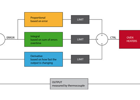
feedback”: at a fixed time frequency the temperature value is read from the sensor (thermocouple) and confronted with the setpoint (ideal targeted temperature). The error is then used to calculate three variables P, I and D. The result of the sum of those variable is then used to know how strongly the heaters should be turned on using a sort of “slow PWM” to drive them via the SSR. It is to be noted that, while in a standard PID algorithms all three components are calculated based only on the error, to improve the response in our PID we decided to calculate D using the difference from the CURRENT OUTPUT value and the LAST OUTPUT value, following a technique also known as “Derivative on Measurement”. Since PID variables may become very large, they are also limited to a maximum value of +/-999. Keep in mind anyway that a PID value of 400 (sum of P,I,D) will turn on the oven constantly, so your values should remain much lower than maximum at any time. Before proceeding to tuning X-toaster we will need to understand how PID variables change the behavior of the oven without using complex math and simplifying everything as much as possible: our goal is to be able to understand enough of the matter to be able to tune it. For a more precise and complete analysis you can read some of the many articles around the web or you can refer to some academic literature on Controls System and Automation.  

Proportional Term

This is the easier to understand. You simply have to multiply a Kp constant with the measured error at any given time. Try imaging when you are driving a car and you want to reach a steady and fixed speed: at the start you would press your foot on the pedal with a large intensity (large error). While the speed increases over time (the error gets smaller) you surely will decrease the pressure on the pedal to have more control. You are simply using a P control. Kp tells you how strongly you have to react to errors by pressing the gas pedal more or less aggressively. When you start your car you never press your pedal all the way down: tuning P means searching a value for Kp large enough to let the speed rise quickly but not so much that you will reach a point where the car becomes uncontrollable. In our oven the main problem with large Kp values are big overshoots because of thermal inertia. In the car example temperature would be more the road traveled than the velocity: if you want to reach a certain distance, even by releasing the gas pedal your car is still travelling because of its inertia: by reducing your Kp the car is more controllable because changes are slower.

Integral Term

The main problem in using only a P term is that, when you reach the target speed in the previous example the error become zero. By definition then, you will instantly and completely release the gas pedal (remember that with P you are simply multiplying the error by a constant Kp). As soon as you release the pedal the car starts to decelerate, the error changes and you will press the pedal again. Of course this is not how people drive because by doing this you are introducing a bad oscillation on your car speed. The integral term helps in removing steady state errors. Let’s see how it can help with our speed problem. I is calculated by multiplying a Ki constant with the sum of all the errors measured during time (if you draw a graph for the "error function", I will be the area under the graph itself, hence “integrative”). You can easily see that I will increase over time, while there is an error, and will become a fixed value when the error becomes zero. Well, this is exactly what we needed with our car: when you reach targeted speed, the error becomes zero. You still have a P term equals to zero but an I term which is not zero so you are not going to release the pedal but, depending on how big is your Ki constant, you will keep on pressing the pedal at a bigger or smaller angle. Tuning I means searching the Ki constant which allows you to have a pressure just right to maintain the speed.  

Derivative Term

We have seen that when the speed changes too fast your car is difficult to control. By using lower Kp values you can improve things a little bit, but everything is less reactive and travelling a certain distance would require too much time. We need a way to keep reaction fast but to counteract changes too big to handle. In our PID version, D is the difference between the output value and the previous output value, divided by the time between the two measurements and multiplied by a constant Kd. If you can visualize it in a graph you can easily recognize it as the derivate of the output function over time (supposing a very small interval between measurements): it tells us how big is the slope of the tangent line to the "output function" for every single moment hence how fast the output is changing. Well, this is exactly what we needed: when the output function is rising D is negative, when it is falling D is positive, when the output function rises or falls gently D becomes almost zero, when there are fast changes D becomes very large. In our car example, at the start when the error is large the controller tells us to press heavily on the pedal. If the speed is not changing quickly we will keep on pressing the pedal but if the car starts moving at high speed we will instantly lower the pressure on the pedal because of the big negative D term now summing with P and the speed will increase more slowly. When the speed is reached, if for some reason your car slows down a little bit, D term will be small enough to allow for a quick speed recovery due to a still big enough P. Tuning D term means searching a value for the Kd constant high enough to counteract for big reactions due to P, which usually brings big overshoots in temperature, but low enough that P is not affected too much that the heating becomes too slow.  

In Short:

ERROR

is the difference between the SETPOINT (target temperature) and OUTPUT (value read by the thermocouple).

P - PROPORTIONAL TERM

tries to correct the error by applying an influence proportional to the error itself

I - INTEGRAL TERM

detect how error changes over time and tries to counteract steady state differences

D - DERIVATIVE TERM

tries to counteract abrupt changes imposed by the proportional term P, I and D are then summed together to obtain a numerical value. That value (let’s call it PID value) is then used to control the heaters via PWM: larger PID values impose the heaters to stay ON for longer PID tuning is the process of finding the right values for the three terms Kp, Ki, Kd.  

An Improved Controller

A lot of reflow ovens, even many industrial ones, can live with just a PID controller for a good reason: they have the ability to not only add heat but also to remove it. Toaster ovens can only turn on the heaters and for that reason a PID controller may often become very difficult (if not impossible) to tune properly. Thermal inertia and hysteresis are your worst enemies. Turning on the heaters make the temperature on the PCB rises only after a period of time and even when you turn off the heaters the temperature on your PCB usually continue to increase with the result of nasty overshoots and burnt components. To solve the problem we added a few more controls:  

Overshoot Compensation

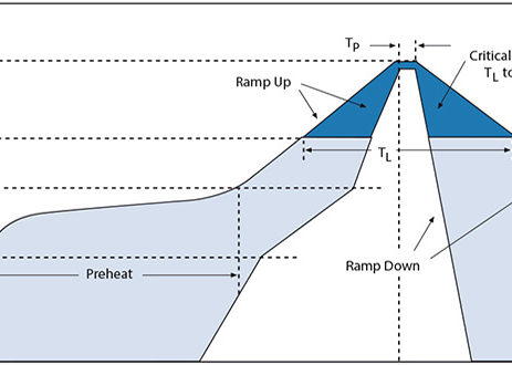
Overshoots in reflow profiles are usually observed in the reflow phase, when your oven is asked to stop rising temperature and maintain it at a steady level for a period of time. While small overshoots of 2/3°C are usually perfectly ok, if you observe more than 5°C with a standard PID controller you would have to start over the tuning process even if the other phases were perfect. By using the overshoot compensation feature you can effectively change how the PID controller reacts only during the reflow phase by lowering the target temperature only where it is overshooting.  

Previsioning

The practical result of hysteresis is that there is a lag from the ideal target profile and the real curve we can observe as read from the thermocouple. When the heaters are turned on and off, the temperature on your board will take a few seconds to change proportionally. This time-shift in the output temperature can be compensated by using the previsioning feature. By using only a standard PID controller there is no way to compensate for it.  

Ki Limit Factor

Since the only steady state to keep in a reflow profile is the short one in the reflow phase, integral term is usually kept at minimum to improve the system response and to make tuning easier. Sometimes though, for certain application which requires both longer phases with a constant temperature AND steep temperature gradients, tuning may become difficult because you need higher ki values for the constant phases but those higher values tends to create overshoots when there are changes. Moreover, since it is not possible to actively take the heat out of the oven “I” term tends to grows over time to very large values which results in the oven heating even during overshoots. Ki limit factor is a constant which come to play when an overshoot occurs: the bigger you set this parameter the faster the value of “I” returns to zero during any overshoot phase. Please note that this parameter is usually not required for reflow soldering and it should be kept to zero (disabled).  

Smooth Radius

This parameter changes the ideal profile by smoothing the knees around the nodes. It helps preventing lags and overshoots by “anticipating” what will be required from the next phase.  

Preheat Until

This parameter acts at the very beginning of the reflow process. It simply bypass the PID controller and turn the heaters to a fixed ON until the chosen temperature, effectively converting the controller in an “open loop” mode. It is useful to prevent big integral summing and to quicken the heating at the start. You should use a value big enough to just reach the same slope of the first segment before giving control back to the PID.  

Fixed Ramp Up

This parameter acts at the beginning of the ramp up in the reflow phase. PID controller is bypassed and the heaters are turned to a fixed ON for the specified amount of seconds. This is useful to improve react time of the oven during the most difficult part of the reflow profile. Please note that this parameter overrides completely both your profile and any overshoot compensation values: if you set it to a value too large your temperature will rise without any control! Before using it with a real reflow process be sure to test it accurately.  

PID Tuning your X-toaster Reflow Controller

PID tuning may be a little bit tricky. Before going any further be sure to know and understand: -    Your oven capabilities, the rate at which it can ramp up -    What is the profile that you are going to use: temperatures and time intervals between each node. -    How a PID controller works and how the constant Kp, Ki and Kd will affect the behavior of the oven Be prepared for a few test runs and always let the oven cool down to at least 35/40°C before proceeding with another test. The process of tuning may take from 30 minutes to a few hours, mostly because you have to let the oven cool down before starting a new test. Keep a cellphone or a camera at hand and shoot a photo of the display at the end of every test to keep tracks of your progress. Always check the calculated values on the display, they can tell you what to change. Reference values for the PID parameters are: Kp:    15~90, it depends on how much your oven is powerful and on how much inertia it has. Ki:    0.01~1, it can be increased for different purposes apart from reflowing. Kd:    1/5*Kp ~ 2*Kp, usually higher with powerful heaters and lower for weak ovens. Your specific oven may require larger or lower values than those specified above. Remember that changing the value of a constant also change the behavior of the others: the entire controller is dependent upon the values and the correlation between the three. For reference these are the typical effects of increasing each variable: Make sure that the profile you are using is compatible with your oven maximum capabilities. 
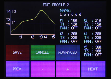
Program the profile in your oven starting from the last node, you won’t be able to set the time one node later in time than the following one. Once the profile has been programmed save it and enter the advanced options screen.  

Let's start...

Let’s start with the “Preheat Until” parameter. We are aiming for a value high enough to quickly bring the oven to temperature and to “move” the heaters from their steady state ambient temperature giving them some inertia. Set this value to 60°C. The “Fixed RampUp” parameter will be useful during the most important ramp of the entire reflow process, start with a value of 5s, we will tweak it later. Ki limit factor is not usually needed for reflowing, set it to zero. Set the “Smooth Radius” to 5s, again we can increase it later if needed. The “Previsioning” parameter is strongly dependent on the size and internal mass (inertia) of your specific oven. Set it to 7s as a starting point, we will probably increase it later. Leave “Overshoot Compensation” to zero, before changing it we need to know if and how much we are overshooting during the reflow phase. Set Kp=15, Ki=0 and Kd=0 Save and start a reflow process with the programmed profile. The first thing to check is the “Fixed RampUp “ parameter. You can recognize its influence because the curve is drawn in pink instead of red and, while it is acting, all PID values are MAN (manual). This parameter should act until the slope of the output is more or less equal to the slope of the first segment of the profile. If it is too high you will get overshot. Observe its behavior, abort the session, change the parameter and start again until you obtain what we are looking for. Now let’s focus on the PID controller itself. By now we only enabled P term with a small Kp constant which will probably be too weak. Increase its value until the red output curve is able to follow the green ideal profile. A few overshoots over the nodes are ok and will be addressed later. If Kp is too low you will observe slow rises and output will mostly be under setpoint. If it is too high there will be oscillations in the output. If you notice a “shift” in time between the ideal profile and the output you can adjust it by changing (increasing or decreasing) the “Previsioning” parameter. Once you have a value for Kp we can try to deal with the overshoots that you probably have. Let’s change the value of Kd to 1/5*Kp. And start a test session. Increase Kd until the overshoots are gone. The effect of increasing Kd is to counteract Kp action when the output is changing very fast. As a result you will probably get a slower response during the preheat phase and the ramp up of the reflow phase. To compensate for it you can increase the “Preheat Until” and the “Fixed RampUp” values. If higher values of Kd are introducing oscillations try increasing Kp again. As always proceed in small steps. If your output is almost perfect but you are still observing some small overshoots over the nodes and the ramps are too late in respect to the ideal profiles try increasing the value of “Smooth Radius”. At this stage you should have a nice output until the reflow zone, where maybe you still have to work with the steep rampup and the overshoot. If you notice that the ramp is not heating fast enough to reach targeted reflow temperature in time try increasing the “Fixed RampUp” value. If the temperature is overshooting take note of how much you have to compensate for it and program the “overshoot compensation” parameter with that value. We still have to deal with Ki. As we saw, the integral term of our PID is used for steady state error compensation: since the only constant temperature in our profile is during the very short peak of the reflow phase you can probably leave Ki to zero and still have a perfectly nice output. If you observe some kind of oscillation during the constant part of the reflow phase you can improve it by increasing Ki. Start from a very low value, something around 0.01 and increase it in small steps until the oscillations are gone and the constant temperature is kept nicely. By increasing Ki you may start to have some new overshoots in your output. If that happens increase again Kd a little bit until they are gone. If the output oscillates tweak again Kp increasing it again in small steps. When the output satisfy your requirements you are finally ready for your first reflow. Congratulations!  

Some Basics on Reflow Soldering

PCB-solder-paste

Why Reflow?

Because it is easy, fast, reliable and gives professional results with very little skills to master. While many SMD components can be soldered with just a standard iron this is generally a very slow process. It also requires some skills to be able to solder smaller components and high-density pins. Some footprints like QFN are very difficult to be soldered with an iron even for a trained technician and often those joints are not good enough even for prototyping purposes. BGA components are of course impossible to deal with and for them a reflow oven is a must. Reflow ovens are the first choice in the industry for production and prototyping, the only downside are their cost and the costs related to reflow technique: you are going to need a stencil for every board and you need to use solder paste which is generally quite expansive. Lately these costs, thanks to some Chinese production facilities and resellers (like Elecrow, SeeedStudio, ITead, etc…), have been lowered from several hundreds of dollars for a steal stencil to less than 20 USD, allowing even hobbyists to build devices with modern and difficult footprints. The only high cost device to buy is a reflow oven. Industrial ovens usually costs more than 1.000 USD and the cheaper Chinese alternatives on the market (which still are quite pricey, around 400/500 USD) are simply too buggy and do not have a build quality good enough for a reliable (and secure) use. A toaster oven conversion is usually a much cheaper (and often better) alternative, but to be able to control the temperature to follow the suggested thermal profiles you are going to need a controller capable of compensating for the high thermal inertia usually related to cheap mass produced food ovens. These toaster ovens also transmit heat mostly by radiation than convection and this is another factor to take into account when building a controller. X-toaster has been designed to follow any reflow profile, to be adaptable to any oven and to compensate for inertia and hysteresis.  

Things to Know

When dealing with reflow soldering there are some things to know which usually are not needed when hand soldering with an iron.

Moisture Content

The first is that some components are sensible to thermal chock and the moisture content of their packages may be an issue. When you order some big microcontroller from Digi-Key or Mouser they usually come in a sealed bag with a humidity indicator and a desiccant pack inside. That’s because the moisture in the package when exposed to high temperatures vaporizes and, if you do not give this vapors enough time to exit the package, the result could be a cracked microcontroller. This lead to the first rule: only open these packing when you are going to solder them on the PCB and check the indicator that the moisture has not gone over the maximum allowed percentage. If you have a lot of components to be soldered in many PCBs during more than one day, always use an ESD safe sealed bag and keep them in it, with the indicator and the desiccant. If you have some sensible components sitting in a box for more than a few days you should try to let the moisture in it evaporate gently before attempting any reflow. X-toaster comes with a preprogrammed desiccant profile to keep the components at 125°C for 60/90 minutes. Even so keep in mind that this is not an ideal process and that micro fractures could be forming.

Hot and Cold Spot

It may be quite difficult, even with big professional ovens, to keep a uniform temperature across the entire PCB. When using a toaster oven this problem can cause some serious issues like pads where the solder paste do not reflow correctly or, even worst, components which overshoots the target temperature. Moreover, since in the toaster ovens the heat is transferred mostly by radiation, remember that bigger black components heats faster than smaller ones. Ideally you should measure temperature over the entire board and across every component to be sure to have a profile with a peak temperature high enough for reflowing but not too high to cause thermal shock on the bigger components. Of course this is not very practical and you should be ok by following a couple of simple rules: If you get unsoldered pads but you are already hitting peak temperature try to make your profile last a little longer for every phase (while keeping it inside the maximum limits). This is usually enough to have the entire board heat mostly at the same temperature. A convection fan may help in spreading the heat with more uniformity: if your oven have one make some experiments turning it on for one or more phases of your profile. Check the tray you are using to sit the PCB inside the oven. The standard toaster oven tray (simply made with steel bars) sometimes absorbs too much heat and you get cold strips where the PCB come in contact with the tray bars. If this is your case build another tray with some steel mesh or try to raise the PCB from the tray with some metal spacers. When designing your board keep in mind that large ground planes absorb much more heat and inertia may cause the pins sitting directly on these planes to overshoot. If you have such problems do not put your pads directly over these planes. Instead connect them with short tracks and eventually try to use thermal reliefs.  

Leaded and Lead-Free

Until a few years ago, every solder joint were made with Sn-Pb alloys and everyone where quite happy about it. Then someone started to think about all the electronics discarded in the bin every day by billions of people and the consequent lead pollution. This (and a few other reasons) brought to the concept of RoHS and lead-free electronic and the Sn-Pb was substituted with other alloys like Sn-Ag-Cu. Today leaded solder is not allowed by laws of many countries, particularly in the European Union and, even if you live in a country where leaded solder medium are allowed, you should consider using lead-free solder paste. Lead poisoning is something you should be concerned about, especially if you work in a home-lab. When absorbed by your body, lead is a cumulative poison affecting your health in several nasty ways. Lead poisoning is not easy to recognize and children are particularly vulnerable to lead, which impede their brain development. The main problem in using lead-free solder paste is the higher temperature needed for reflowing. When using lead-free pastes you need to use profiles with high peak temperatures (around 250°C) and you have to take special care to make sure that overshoots are kept to a minimum and timings are carefully respected to avoid damages to your PCB and components. When programming your reflow profiles, you should refer to the suggested profiles published by the producers of your solder paste and by the manufacturer of the components of your board. If you have no access to those documents and for general reflow applications you can always use the standard profiles published by JEDEC.  

JEDEC Standard Profiles

The JEDEC Solid State Technology Association, formerly known as the Joint Electron Device Engineering Council (JEDEC), is an independent semiconductor engineering trade organization and standardization body. They published a few documents on reflow soldering with a couple of leaded and lead-free standard profiles you can refer to when programming X-toaster. By looking at the graph (JEDEC/IPC J-STD-020) you can easily understand that there is not a strict curve to follow, instead there are areas where to fit you profile. Even peak temperature (Tp) is not fixed for every situation, but changes depending on the packages thickness and volume. When programming the nodes on X-toaster these will be the corresponding phases:

PREHEAT

Flux solvent are evaporated during this phase and your board is quickly brought to a little bit more than half reflow temperature

SOAK

Solvents evaporation completes during this phase. Flux starts its deoxidizing action on parts to be joined and board is kept to an almost stable temperature for a certain amount of time to minimize thermal gradient

REFLOW

In the blue zone there is the actual melting of the alloy which forms the mechanical/electrical joint

COOL-DOWN

A quick cooling would be desirable to create finer grain structure and stronger joint. This is actually not always possible with toaster ovens where there are no exhaust/cooling fans. All you can do is simply open the oven’s door and wait until the temperature is low enough.  

LEAD-FREE Parameters

On the table we can identify the maximum ramp up and ramp down rate (3°C/s and 6°C/s respectively) which, in our case, are not a big problem because you will hardly be able to obtain steeper rates with toaster ovens. What may be a problem instead are maximum time above liquidus (217°C, 60-150s max) and maximum time within 5°C of peak (Tp). If your oven is not powerful you could be forced to increase those values to allow temperature to raise enough. That is why choosing a powerful and small (quick) toaster oven is so important for reflowing. You should be able to reach more than 1°C/s when ramping up (ideally at least 1.5°C/s) with your oven. If you can’t you should consider another oven or adding more heating elements.  

Sn-Pb Parameters

As expected Sn-Pb parameters are much more “relaxed”. The most important factor is the peak temperature of only 225/240°C compared to the much higher 245/260°C of the lead-free profile. JEDEC recommends shorter time within 5°C of Tp and also shorter time above liquidus compared to the lead-free parameters, but if your application is not critical you should be ok with longer profiles. If your oven is not powerful enough for lead-free alloys and you are not willing to change or mod the oven, Sn-Pb may be your only choice for reflowing.  

Draw your Reflow Profile

We have seen that you have some kind of freedom to draw a profile suittable for your applications and your particular oven. At this point you really need to know what is your oven capable of, what kind of solder paste you will be using and which component sizes will be mounted on your board. Knowing the rate at which your oven can ramp up and cool down is easy enough using X-toaster controller. After setting up your oven, controller and thermocouple like suggested in the article "X-toaster Installation & Wiring", program a profile with a high Kp and a steep temperature rise (5s) to around 150°C and let it run for at least a couple of minutes or simply set the "Preheat until" parameter to 150°C. Your oven will be fired on constantly and you will be able to observe how much your oven is ramping. For the cooldown you can do the same in reverse: at the end of the previous profile set a steep cooldown to 25°C and make it at least a couple of minutes long. When the last phase start, open your oven’s door fully and you can observe at which rate your oven is cooling. You will probably find that your ramp up is around 1.5°C/s and you are cooling down at no more than 2 or maybe 3 °C/s. It would be pointless to program a profile which your oven will never be able to follow. Make sure to use the previous limits as a reference. If you find that your oven is a little bit slow in the pre-reflow ramp-up you can tweak your profile to make that ramp a little bit easier, for example by using the whole allowed limits for the SOAK phase (150°C-200°C for lead-free and 100°C-150°C for leaded). Special care should be dedicated to the peak temperature. Once you know which peak temperature you a targeting based on your components size, draw a profile which respect the maximum time allowed for it and run a test. If you can, diminish the time within Tp as much as possible. If you observe overshoots try to use the Overshoot Compensation feature in the ADVANCED options. Of course you should also set the PID parameters. These are addressed in the "PID Tuning" article.  

User Interface

User interface is provided by the LCD and four leds. Leds, from left to right:
Orange Mostly red when on. Power on, shows that the board is powered.
Blue Status Led. Used for various pourposes, it is usually on when there are problems with temperatures and when a reflow process is running.
Green On when FAN CTRL is on
Dark Orange On when HEATERS CTRL is on
  x-toaster-leds 
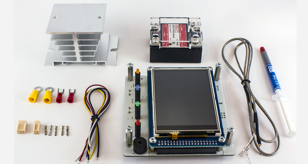
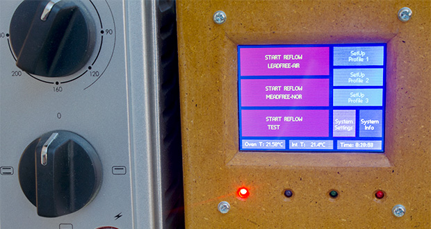
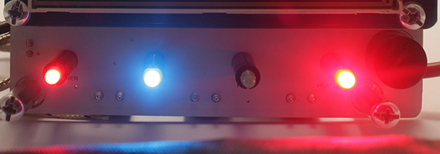
Please note that all the leds has been polarized to have mostly the same light intensity except for the SSR HEATER which is a little bit brighter (electricity is flowing, heat is generated) On the LCD you can navigate through the menu with the touchscreen:  

Main Menu

From here you can check the oven’s temperature as read from the thermocouple, the onboard temperature sensor readings and how much time passed since the board was powered. Three red buttons on the left will start the respective reflow sessions, while three blue buttons on the right allows the user to reprogram the profiles with their names and their advanced parameters. The purple button will allow to change general system settings and the grey one is used to overview some system info and all three temperature sensors.  

Setup Reflow Profile

Each profile has five time nodes arranged in this way (t0 is the moment in which the reflow profile is started, for t0 temperature is automatically read from the oven): t0-t1:  PREHEAT PHASE t1-t2:  SOAK PHASE t2-t3:  RAMP-UP PHASE t3-t4:  REFLOW PHASE t4-t5:  COOLDOWN PHASE Each of these five nodes can be programmed with the desired time/temperature and for each of these phases you can sepcify if the oven’s fan has to be turned ON or OFF. You can move between the options using the “PREV” and “NEXT” buttons, values are changed with the “+” and “-“ buttons. The graph drawn on the top-left corner shows a visual preview of the profile you are programming and is refreshed whenever a change is made or when you touch it. When you are satisfied with your profile you can save it to EEPROM by pressing the “SAVE” button which will bring you back to the main menu or you can press the “ADVANCED” button to save it and enter another page in which you can modify the advanced parameters for that profile.  

Advanced Reflow Parameters

Preheat Until

Used to keep the oven ON from the start of the reflow session, discarding any PID result, until a certain temperature is reached. This may be useful to avoid big Ki summing due to starting inertia and to speed up initial heating. When set to 0 this control is disabled.

Fixed RampUp

Like the “Preheat Until” parameter this control allows to keep the oven ON during the RAMP UP phase but, instead of a temperature you can specify for how many seconds you want to discard PID results. This may be useful if you needed to use big Kd values to limit overshoots but you need to quickly heat up the oven to reach reflow temperature. This control is disabled when set to 0.

Ki limit factor

This parameters starts acting when there are overshoots, lowering Ki at a faster rate than normal. Disabled when set to 0.

Smooth Radius

Since your reflow curve is going to be 5 segments delimited by the nodes, the “steepness” of the knees may result in overshoot and/or undershoot. This parameter helps in smoothing your profile by drawing another segment which replaces the knees around the nodes for the programmed seconds. When set to 0 this control is disabled.

Previsioning

A big problem with toaster ovens is their large thermal inertia which leads to time lags of the output. If you can observe this kind of behavior by changing this parameter you can effectively shift your real observed curve ahead or later in time in respect to the target ideal profile. For larger oven this parameter give good result with values of 10~18, smaller oven having lower inertia may be ok with a value of 2~10. A little bit of testing is necessary to fine tune it. This control is disabled when set to 0.

Overshoot Compensation

Like the Previsioning Parameter, Overshoot Compensation allows to compensate for thermal inertia in the REFLOW PHASE where usually there is a target temperature to keep and maintain for a given time. This problem is also known as Thermal Hysteresis: your profile is almost perfect but when it has to settle at a temperature it constantly overshot by a few degrees. Set this parameters exactly equal to the overshoot you are observing to compensate for it. This parameter is disabled if set to 0.

PID-Kp

The proportional constant of the PID controller

PID-Ki

The integral constant of the PID controller

PID-Kd

The derivative constant of the PID controller  

System Settings

DEFAULT SETTINGS – Restore all system preferences to defaults DEFAULT PROFILES – Restore all profiles nodes and parameters to defaults These are the parameters you can customize in the System Settings Page:

Timeout

How many minutes before the system enters standby/shutdown and the user is asked to take actions

Int Sen MAX T

Maximum temperature reading allowed from the onboard sensor before firing a Temperature Alarm and the user is askedto take actions.

Ext Sen MAX T

Same as Internal, but for the external sensor

Oven MAX T

Same as onboard and external sensor but related to temperature read from the thermocouple.

Buzzer Volume

increase or decrease buzzer volume

Offset Temperature

Thermocouple reading error is not linear over the entire temperature range, but if you can observe a fixed offset in respect to other sensors you can adjust it from here. It can be set both with negative or positive values.

Draw Real Curves

If, during reflow sessions, you want to display both the ideal curve (only defined by nodes), and the ideal curve modified by advanced parameters (except previsioning), by setting this value to YES you will see the ideal green curve, a modified yellow curve and the real measured values in red.  

System Info

The "System Info" page will show you some information about the connected DS18BXX sensors and the stored parameters for the touch screen calibration. By pressing the "Recalibrate" button you will enter a page with a 5 points recalibration routine. If, for some reason, you mess up with the recalibration parameters and you are no longer able to enter this page you can shut down the board, touch the screen and keep pressing while the controller is powered up. It will automatically enter the recalibration page.  

Start Reflow

Reflow page is mostly occupied by the time/temperature graph in which you can confront the target ideal temperature (green) and the measured temperature from the thermocouple (red). You can also check the numerical values in the bottom left of the screen where in green you can read the ideal target temperature (calculated against the advanced parameters) and in red the measured temperature. The second grey square at the bottom left shows the internal and external temperature sensors values. On the third grey square, as a reference, saved PID constant are shown. The bigger red square stops the reflow process if needed. On the top left you can read the custom profile name, in the center the calculated PID parameter and at right time in seconds from the start of the process. Calculated PID values are a must when tuning your controller: by visualizing them you can see which one needs to be lowered or increased. During COOLDOWN phase the controller will ask to open the oven’s door.

X-toaster Installation & Wiring

toaster-reflow-oven-wirings

Safety Notes

[box type="warning"]Please understand that, while X-toaster is a low voltage device and no high voltage source should be connected directly to the board, to build a reflow oven you will have to deal with mains power and connections. Mounting and using the controller involves two deadly hazards: fire and electrocution. X-toaster is not an end user product. Instead, it is a component which should be used to build a finished device (a toaster reflow oven). As such it is intended that you are a well trained electrical engineer who knows how to deal with mains power and industrial devices and production. Do not take the chance of risking your life: if you do not know what you are doing or if you are not sure about something seek for the advice of an expert technician in your area. If this is not possible please do not use this board.[/box]

Consider an External Enclosure

Toaster ovens are not designed to be modded for reflowing. While it could be possible to fit the board directly into the oven’s chassis we strongly advise you to consider buying or building an external dedicated enclosure. There are three good reason for this: 1) Temperatures inside the oven could become too high (above 50°C) and the board may be damaged by repetitive exposures to such temperatures. In fact, all electrical connections inside an oven are made with high temperature resistant wires. If you decide to mount the board inside the oven you should always use high temperature wires and you should find a way to insulate the board from the heat generated. 2) Apart from the board itself, you will have to mount at least an SSR with its heatsink and a power supply. Usually there is not enough space inside a chassis to mount all these boards and components AND the insulation WHILE keeping all the installation clean and safe with a sufficient air flow. 3) With such a small area inside the oven chassis it would be difficult to keep the right and safe distances from high voltages boards and wires and the low voltage controller part. As always think about safety first and try to imagine worst event that could happen, like an high voltage wires disconnected which come in contact with the controller board. If you are still willing to mount the controller inside the oven, you should at least use the onboard temperature sensor to ensure that the maximum temperature of 70°C is never reached (check “User Interface”). Even so, keep in mind that your board life will be considerably reduced. A slightly better option would be to install the SSR inside the oven and the controller in an external enclosure. Even when you do so, remember that the SSR we are supplying in our kit is rated for a maximum operation of 80°C, to keep it to a safe temperature you should use an external sensor (connecting it to the “EXT SENSOR”) and position it in firm contact with the SSR heatsink using some fastener to secure it in place and maybe some heat transfer compound. You should set the maximum temperature using the user interface to a maximum of 60°C/65°C.

Suggested Enclosure and Dimensions

In another article you can find the layout for a front panel. You can use that drawing to drill holes and cut the LCD opening in the right position of your front panel. That drawing also indicates the minimum internal width and height of an enclosure to be able to accommodate the controller. The minimum internal depth of the enclosure depends on which other boards and components you are going to fit inside it. If you are going to use an external 5V power supply (a wall cube) and you are going to mount the SSR inside the oven, the depth of the external enclosure can be kept to a minimum of 50mm/60mm. Of course having many smaller enclosures and devices around may not be practical so you would want to use a bigger housing and to mount everything inside it. Whichever solution you are going to adopt, keep in mind these basic rules: 1) Use the right wire gauge and type for your connections, especially those involved in high voltage. Know how much power your oven is going to absorb and dimension your wires accordingly. 2) Keep your connections short enough to reduce EMI and power dissipation but long enough to create comfortable connections. 3) Use plastic strips to tie cable together in firm but unstrained positions. 4) Always provide for some kind of strain relief mounting to cables going out your enclosures. 5) For mains power and for all cables mounted inside the oven always use crimped connectors, never use soldered connectors. 6) Be sure to always connect to earth all metal parts involved in your enclosures and always double check those connections. These are your lifesaver when something go wrong: check them again! 7) if you can, use a metal housing (connected to earth). They are fire-safe, stronger than plastic and wood and provide better shielding and better heat dissipation. 8) make sure that all bolts and screws involved in your assembly are tight but not overtight. 9) always use a multimeter and check your connections as you go through the assembly and before connecting any power source. 10) inside the oven use only high temperature cables. 11) you should always identify high voltages area inside an enclosure and isolate them as much as possible from low voltage wires and boards. Never tie together wires of different voltages and never position an high voltage board (like a power supply) near a low voltage board (like the X-toaster controller)

Electrical Connections

In the kit you will find the right female connector which mates with the onboard male. Please note that it is a polarized connection and, even if the board is protected against inverted power, you should check the polarity of your power supply and connect it accordingly. To test the board you will also have to connect the thermocouple otherwise an “Hardware Error” will be fired. The thermocouple is a k type probe and it also have a polarization which you have to respect. Usually the blu wire goes in the “-“ and the red wire is to be connected to the “+” side. The HEATERS CTRL and FAN CTRL connectors should be connected respecting the polarity of your SSR: “-“ with “-“ and “+” with “+”. For a standard installation the PDI connector should remain unconnected. The EXT SENSOR has 3 pins: D (data), V (Vcc) and G (GND). You can use any DS18XX sensor or probe, you just have to respect the polarity indicated on the board. The SSR should be mounted on top of the heatsink using screws and the supplied compound. Note that the SSR "cuts" the brown wire which is the PHASE. The blu wire (NEUTRAL) should be connected straight to the oven. To crimp connectors to wires you should use a proper crimping tool. Avoid the use of pliers.

Thermocouple Positioning

If you decided to use an unmodded oven the only way to put the thermocouple inside the oven is through the main door. Make sure that the door remain as closed as possible but do not force it to avoid any damage to the sensor wire. The supplied thermocouple is not grounded, it is not possible to use grounded thermocouples with X-toaster. You can decide to position the thermocouple in free air or to attach it to a test board. We suggest you to mount the thermocuple in free air: this is the most common situation and it allows to directly use the profiles suggested in the datasheets of the electronic components on your board. If you need a very precise temperature reading you can use a test pcb similar in size and copper surface to the ones being soldered. The tip of the probe should be positioned inside a grounded via or a small plated hole of another test board, and secured with some kepton tape. You may also want to use a little bit of heatsink compound placed on the tip to ensure an optimal thermal conductivity.    

Modding a Toaster Oven for Reflow Soldering

modify-toaster-reflow-oven 
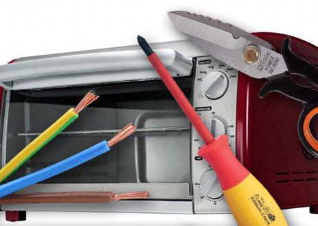
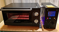
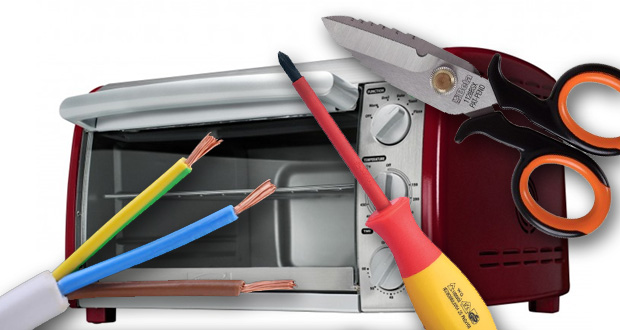
You do not have to mod your oven to be able to reflow your board. If you can turn on your oven from the knobs and set it to “always on” at maximum power, you can simply use the supplied power cord to connect the oven to the SSR and, in turn, to the controller. This is the simpler, safer and quicker method. If you do not have a good reason to start unscrewing the oven you should leave it “as is”. At least, before opening the oven and start modding it, you should try to make a couple of test to see if the oven needs some modding and to understand which kind of modding would be beneficial for you. By modding your oven you could: - add more heaters to improve ramp up speed and reduce cold spots. - add insulation to improve ramp up speed and to easily maintain a steady temperature. - drill an hole to the side or the back for the thermocouple - connect the heaters directly to the SSR bypassing any mounted thermostat and timer - reduce internal volume to reduce thermal inertia - consider adding a convection fan if not already present - adjust the tray height and possibly modify the tray itself with spacers or a steal grill to avoid cold spots on the PCB  

Choose a Toster Oven for Reflow Soldering

Since you will be cooking some nasty things inside your oven you are going to need a dedicated oven for your reflow soldering. DO NOT COOK FOOD IN YOUR REFLOW OVEN! If you have an unused oven lying around you can try to use it before going out and buy a new one, but if you need to get a new oven there are some things to keep in mind when choosing it to buy the best you can for your job.

Controls

toaster-reflow-oven-control-knobs 
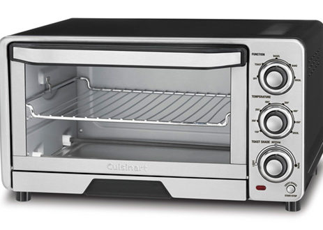
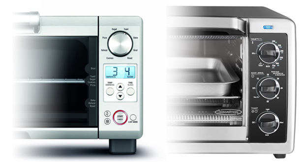
Avoid the new electronics controlled oven with cool displays and touch buttons. You are not going to use those controls and you can save some money by getting a basic one with only manual controls. If do not plan to open and modify internally the oven make sure that you can turn it always on with the supplied knobs. If you want to reflow with lead-free solder paste there is the possibility that the thermostat of the oven will shut it down before the temperature you need to reach. If this happens, you will have no other choice than open the oven and bypass the thermostat control knob.

Dimensions and Power Rating

toaster-reflow-oven-size 
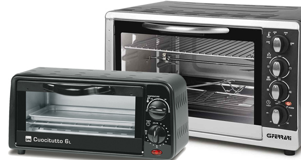
As a general rule, keep in mind that, since larger ovens have more mass, they tend to heat and cool down slower than the smaller ones. In other words they have much more “thermal inertia” which is ok for cooking but definitely you want to minimize it for reflow soldering. Because of that, you may want to start searching for the smaller oven with the highest power rating you can find in the market. Something around 1500W for a small oven is almost perfect. If you really need to use a larger oven you should consider modding it to add some more heating elements but before doing any modification check for your power outlets power rating. If you live in a country where the outlets have a standard rating of 110V/120V@15A you can’t draw more than 1500W and you cannot modify your oven unless you ask your energy supplier to install a 220V/230V power line.

Convection Fan

toaster-reflow-oven-convection-fan A circulating air fan is not needed but it may help to improve heat consistency across your PCB. Industrial reflow ovens basically work by convection. They are designed to minimize radiated energy from the heaters and to use only hot air to transfer heat to the PCB with one or more fans which not only keeps the temperature gradient in the oven to a minimum but also draw the hot air out when there are overshoots and during cooldown phase. A toaster oven on the other hand works basically with radiated energy from the heaters and the small fans they usually come from are often not adequate to ensure a minimum heat gradient. In our tests, we found that sometimes they can help but, depending on the oven and the fan itself, they may cause problem during the liquidus phase. Sometimes they have strong vibrations and sometimes they spin too fast with too much airflow on small areas. Both of these problems usually results in the smaller components being moved out of their places. The only way to know if your oven’s fan is ok is to actually try it. For small PCB with small components you should be ok with the fan OFF. If you have bigger components you can try to turn on the fan during the entire reflow process. If your board has a mix of bigger and smaller components you can try to turn on the fan only during PREHEAT and SOAK. Also keep in mind that turning on the fan usually results in an increase of thermal inertia and tuning your profile may become somewhat harder and, if you plan to use an oven without having to open and modify it internally, there is no way to externally control the fan which is usually always on.

Heaters

toaster-reflow-oven-heaters 
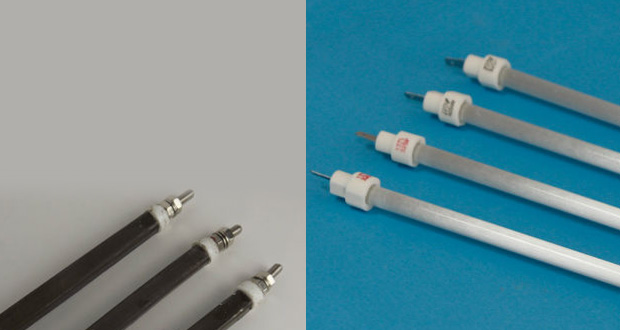
There are two kind of heaters usually mounted inside a toaster oven: the classic ceramic heaters (the ones you find inside your big kitchen oven) and the newer quartz heaters. While both of them can do the job of rising temperature high enough for reflowing, quartz elements tends to heat up and cool down faster. This will improve the response of the oven to your reflow profile so, if you can, get an oven with quartz elements. 
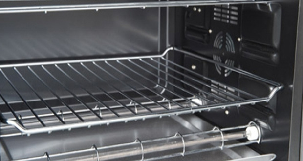
The position of the heaters in the oven is also important. If you have only one heater on the top and one at the bottom you will probably have a few problem with larger boards with some hot spot directly under the heating elements and a few cold spot in the farther locations. Ideally there should be at least two elements on the top and two at the bottom. If you have to decide, it is better to have two heaters on the top and none at the bottom. This will drastically improve heat distribution but could also lead to warped boards for larger PCB (more than 10cmx10cm). Try to choose an oven which is adequate to the boards you are going to reflow.

Mounting X-toaster on a Front Panel

toaster-reflow-oven-front-panel 
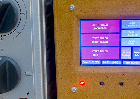
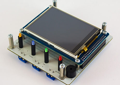
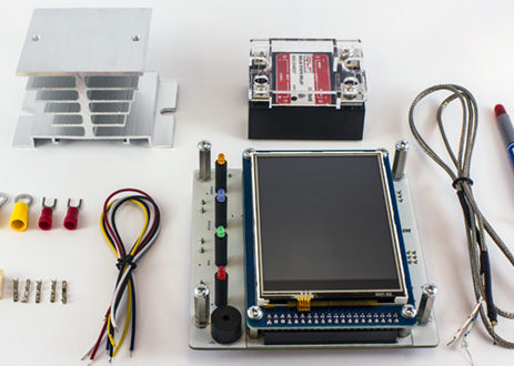
X-toaster has been designed to nicely fit in an enclosure with an inner width of about 100mm and it comes with a set of mounting spacer bolts which allows the LCD and the LEDs to sit at the right height when mounted on a front panel. Mounting holes and LEDs have been positioned around the LCD’s viewing area to provide a symmetrical appearance from the outside of the front panel. For this reason the board will be in an eccentric position when mounted in the chassis.   All spacer bolts are M3 threaded. As a reference when building your enclosure you can use this drawing:   Which will result in this mounting:  

X-toaster Board Layout

 
RESET Reset for the Xmega, not mounted.
PDI Programmer/debugger interface for the Xmega, if you have one of the latest PDI capable Atmel programmer like the AVRISPmkII and the ATMEL-ICE you can use it to upgrade X-toaster with future firmware revisions.
INT SENSOR Populated with a DS18B20+, used to read the temperature around the board. If you are going to fit X-toaster in an hot environment (like inside the oven itself) it can be used to keep track of the temperature and shut the system down if temperature goes above some limit that you can program via GUI.
EXT SENSOR  Unpopulated. You can fit another DS18B20+ to read temperature from another area. Like the internal sensor it possible to set a maximum temperature after which the system has to be shut down. If you mount the controller in a separate box but if you fit the SSR inside the oven, you can use it to make sure that the SSR is not overheating. G: ground, V: 3.3V, D: data
HEATERS CTRL  This is used to drive the SSR which controls the oven’s heaters. Its output is a slow PWM with a peak voltage equals to VIN less voltage drops on D3 and Q4 which results in around 4.70V. Some Chinese SSR are not able to fully turn on and work properly even if they have 3V~32V INPUT written on their labels. If you find that this is the case you may want to short D3 terminals to have a driving voltage almost equals to VIN. If you get our kit with the SSR that we supplied you should not have any problem and no actions is usually required.
FAN CTRL  Used to control the oven’s fan if your oven has one. It is based on the same circuit of HEATERS CTRL so the same considerations about SSR connections are valid. Since this is not switched on and off so often like the heaters you can also use a mechanical relay to drive the fan.
THERMOCOUPLE  You can connect any K-type thermocouple but because we are using a MAX31855 it has to be isolated from GND.
VCC IN  Used to power the board. You should use a power supply with a clean and stable voltage of 5VDC capable of supplying at least 500mA.
 

What is X-toaster?

X-toaster is a controller board designed to convert any common toaster oven into an SMT reflow oven. It can drive two external SSR to enable control of the heaters and, if present, the oven fan. The heart of the system is an Atmel ATXmega128 which can be reprogrammed by the user through the onboard PDI connector. To amplify the signal coming from the thermocouple we selected the MAX31855 which supports any K-type non-grounded probe. There are three profiles stored in EEprom which can be modified and re-programmed whit your own, to adapt the system to various PCBs, solder pastes and ovens. Temperature control is provided by a custom PID algorithm with some unique predictive feature to smooth any fast changing ramps in the profile and an exclusive overshoot compensation. GUI has been designed to work on a 3.2” color touch screen. Safety features include a programmable timeout, two sensors to check for onboard and external over temperature, oven maximum temperature control, and hardware malfunctioning control. [box type="warning"]To install and operate this board it is assumed that you have an adequate knowledge of digital and analog electronics, high voltage installations and SMD technology. If you are not an electrical engineer please do not buy this product and do not use it unless you can get some help by a trained technician. Also refer to the DISCLAIMER section.[/box]  

FEATURES

ATXMEGA128 MCU MAX31855 K-type thermocouple amplifier On Board buzzer for alarms and user notifications Screw connectors for SSRs and thermocouple Onboard 3.3V regulator (5V regulated input) 3.2” Color TFT display with Touch Screen which allows for standalone operations without a PC Fast parallel LCD interface for a smooth GUI Modified PID algorithm to address thermal inertia and hysteresis On Board LEDs for POWER, STATUS, SSR and FAN On Board DS18B20 + 3 pins connector for another external sensor Three pre-programmed profiles for lead and lead-free soldering reprogrammable by the user For a quick and general use there is no need to open and internally modify the toaster oven Ready to be mounted on a front panel, supplied with the necessary spacers Lead Free and RoHS compliant Industrial temperature range: -20°C ~ +70°C Board Size: 98mm x 96.5mm